Water pump driven by compressed air or steam – patented

1. Description of pressure-shock pump - state of the art and shortcomings of the known designs

A pump is a technical device that, combined with an inlet and outlet line, transports a fluid such as a liquid, steam or gas to the inlet of an inlet line and then to the outlet of an outlet line by external energy supply and at the same time enables further delivery by increasing the energy of the fluid (increase in pressure, acceleration). With the exception of the hydraulic ram, the energy supply to the actual pump mechanism takes place by means of a separate energy transport line in the form of a mechanical linkage (supply of mechanical energy), a cable (supply of electrical energy) or a separate fluid line (supply of pressure -Energy). When pumping water from wells, pump systems are divided into two classes: In the first class, the pump is located underground at the bottom of the well. Therefore, the pump must be able to generate at least a pressure that corresponds to the hydrostatic water pressure resulting from the depth of the well. A separate energy transport line must be installed, the length of which is at least equal to the depth of the well. The second class is above ground above the well shaft. The pump then works with a suction mechanism. The maximum delivery height (geodesic suction height) is therefore limited by the vacuum that can be achieved, the local air pressure and the flow resistance to be overcome and is typically less than 10 meters.

2. Which technical problem is solved and how

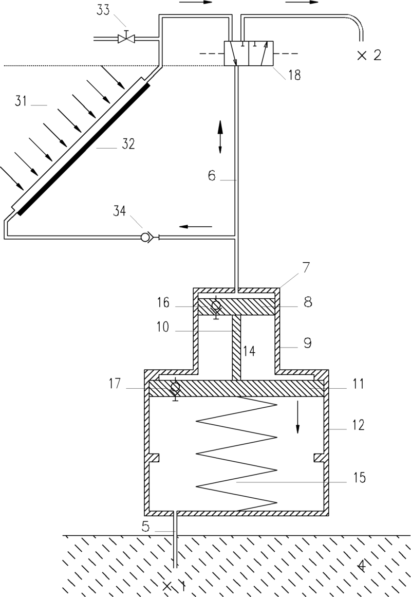
The object of the present invention is to realize a pump without a limited delivery height and without a separate energy transport line, which is driven by pressure surges of a drive fluid in a common drive delivery line (AFL). conveys a liquid, gaseous or vaporous conveying fluid from a starting point A through the AFL to a destination B. In a special embodiment, the drive takes place by means of a solar thermal water vapor generator in an open Rankine-like thermodynamic process. In this case, both the drive and the delivery fluid are water. In contrast to known solar steam pumps with a closed Rankine process (e.g. DE 35 42 865 A1), complex components such as a condenser and feed pump are no longer required. The compensation for the water loss due to evaporation that inevitably occurs in the open system is directly compensated for by the water pumped from the AFT. This allows a structurally simple, solar thermal pump to be realized for pumping water from (deep) wells.

2.1 Structure and components

The machine according to the invention described below is referred to as a pressure-shock pump (Druck-Stoß-Pumpe - DSP). The DSP consists of the pump chamber (7) with a coupled mechanical energy storage (15), the inlet line (5), which connects the output location A (1) with the pump chamber, and an AFL (6), which Pump chamber connects to the target location B (2) (Fig. 1a). At the destination B (2), the AFL is alternately connected to the pressurized drive fluid (3) and the environment for removing the pumped fluid (4) by means of a valve mechanism (18). The valve control is driven either mechanically, electrically, pneumatically or hydraulically. The control is carried out by control electronics or by an automatically oscillating mechanism. The pump chamber consists of a drive chamber (10) and a delivery chamber (13) with volumes VA and VF, the size of which periodically changes between a minimum and maximum value. Both rooms are formed by two piston-cylinder arrangements (8.9/10.11). The two pistons are mechanically connected to a piston rod (14). The design of the two piston-cylinder arrangements is carried out by appropriately dimensioning the diameters in such a way that when the piston arrangement moves downwards, the increase in the delivery volume exceeds that of the drive volume. The delivery chamber is connected to the inlet line or the intermediate antechamber and the drive chamber via a check valve (16, 17). The valves can be arranged outside the pump chamber or integrated into the drive and delivery piston. The two connected pistons are coupled to a compression spring (15), which has a preload at top dead center and an associated force that increases the force acting on the delivery piston due to the hydrostatic pressure of the delivery fluid acting on it over the entire height in the AFL.

2.2 Function

The DSP goes through two process steps: In the first process step (Fig. 1a, cycle A), the AFL is connected to the pressurized drive fluid (3) via the 3/2-way valve (18). The drive fluid flows into the AFL up to the pump chamber. The pressure applied to the drive piston (8) results in a force on it and thus moves it towards the lower end position. The check valve (16) prevents the drive fluid from entering the delivery space (13). The coupled movement of the delivery piston increases the volume of the delivery space and thus creates a negative pressure, which pushes the delivery fluid through the inlet line (5) and the check valve (17) into the antechamber and then into the Conveyor room sucks. At the same time, the spring (15) coupled to the two pistons is tensioned. In the second process step (Fig. 1b, cycle B), the AFT is separated from the pressurized drive fluid by reversing the 3/2-way valve (18) and connected to the environment. This means that part of the drive fluid escapes into the environment and the pressure at the upper end of the AFT drops to the pressure of the environment. The spring tension results in an upward force on the delivery piston. During its upward movement, this pushes the delivery fluid through the check valve (16) into the drive chamber and then into the AFT. Backflow into the inlet line or antechamber is prevented by the check valve (17). After reaching the upper end position, the cycle is completed and begins again. Each cycle, a volume of delivery fluid is effectively transported into the AFT and thus upwards, which corresponds to the change in the volume VFmax-VFmin of the delivery space. After a few cycles, the delivery fluid fills the AFT and finally reaches the destination B. The volume VAmax - VAmin drive fluid with pressure PA is consumed per cycle.

3. Designed as a solar thermal steam DSP

An important implementation of the DSP is a solar thermal water pumping system. The drive fluid, in this case water, is evaporated in a solar collector (32, possibly with concentrating optics and/or tracking) after its initial water filling and the steam is fed to the AFT via the control valve. The AFT is connected to the control valve above the outlet line of the solar collector. After filling the AFT (possibly several pump cycles), the evaporated water is compensated solely by the hydrostatic pressure in the AFT, which pushes the water from below through the check valve (34) into the solar collector. The collector fill level is therefore automatically regulated and depends only on the position of the upper end point of the AFT and possible pressure drops in the check valve.

4. Build a prototype

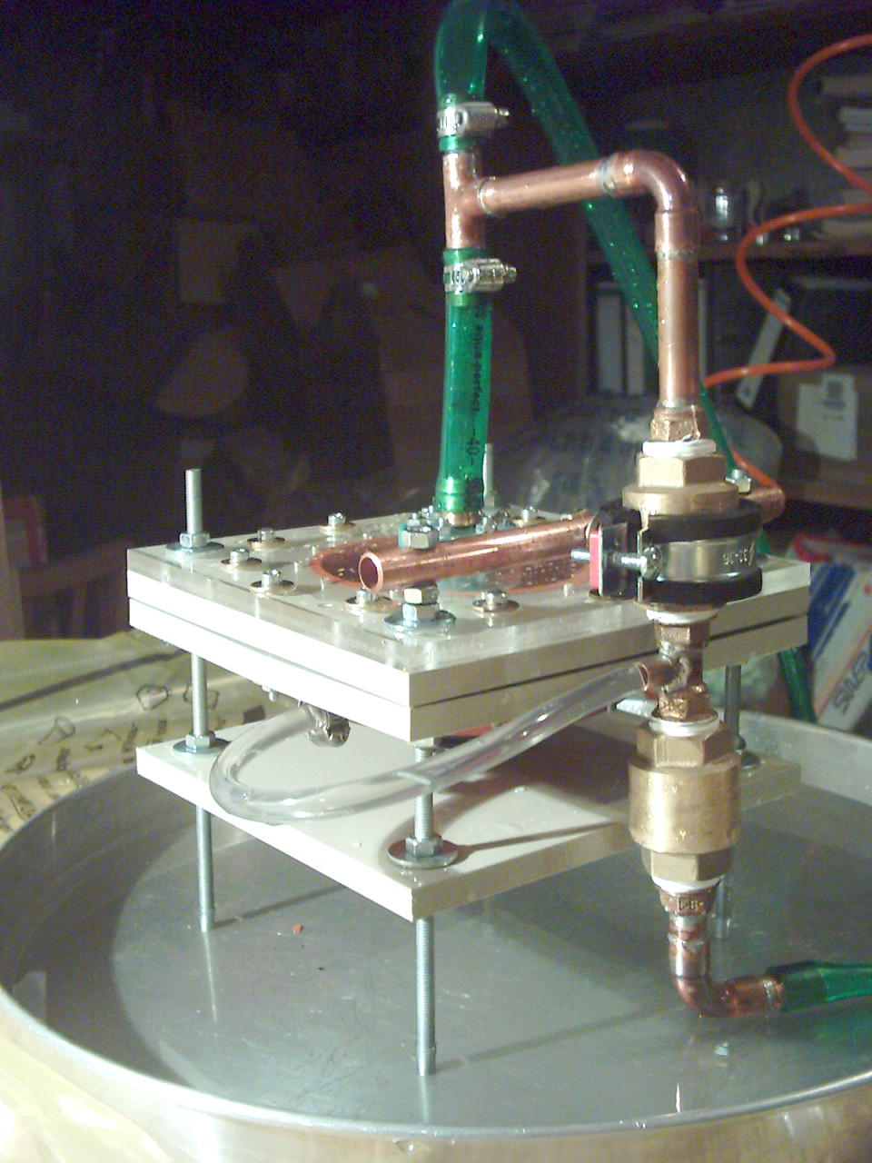
4.1 - Piston/cylinder version

4.2 Membrane version

5. Patent

Declarant
Schmidt, Thomas, Dipl.Phys., 79104 Freiburg

Disclosure document
DE102007022658A1